Add3DPt Objects - 3D 
MiniCAD

VectorScript Declaration:

PROCEDURE   Add3DPt
(   pX :REAL;
    pY :REAL;
    pZ :REAL
) ;

Python:

def  vs.Add3DPt(p):
   return None

Description:

Procedure Add3DPt adds a vertex into a newly created 3D polygon.

Calls to Add3DPt should be made between calls to BeginPoly3D, which initiates polygon creation, and EndPoly3D, which terminates polygon creation. A minimum of two vertices must be created to define a valid 3D polygon object, and calculations may be performed within the BeginPoly3D-EndPoly3D structure, providing additional options for vertex generation.

説明

BeginPoly3DとEndPoly3Dの間で使います。

Parameters:

p Location of 3D vertex. 頂点の座標

Example:

BeginPoly3D;
     Add3DPt(0,0,0);
     Add3DPt(2,0,0);
     Add3DPt(2,2,0);
     Add3DPt(1,3,0);
     Add3DPt(0,2,0);
     Add3DPt(0,0,0);
EndPoly3D;


See Also:

BeginPoly3D   EndPoly3D  


  AddVertex3D Objects - 3D 
MiniCAD6.0

VectorScript Declaration:

PROCEDURE   AddVertex3D
(   objectHd :HANDLE;
    pX :REAL;
    pY :REAL;
    pZ :REAL
) ;

Python:

def  vs.AddVertex3D(objectHd, p):
   return None

Description:

Procedure AddVertex3D adds a 3D vertex to the referenced 3D polygon object.

説明

ハンドルで指定した3D多角形に頂点を追加します。

Parameters:

objectHd Handle to object. 3D多角形のハンドル
p Location of 3D vertex point. 頂点の座標

See Also:

Add3DPt  


  BeginMesh Objects - 3D 
MiniCAD

VectorScript Declaration:

PROCEDURE   BeginMesh
;

Python:

def  vs.BeginMesh():
   return None

Description:

Procedure BeginMesh begins the efinition of a 3D mesh object in Vectorworks. Any 3D point or planar object call after BeginMesh will be included in the mesh object.

A mesh object allows the user to select and manipulate each vertex within its wire-frame model.

説明

この手続きを実行した後、EndMeshが実行されるまでに作成された図形をもとにメッシュ図形を作成します。

Example:

BeginMesh;
ClosePoly;
PenSize(1);
PenPat(2);
FillPat(0);
Poly3D(0',0',4'-0",4'-0",0',4'-0",4'-0",-4'-0",4'-0",0',-4'-0",4'-0");
Smooth(0);
Poly3D(0',0',0',4'-0",0',0',4'-0",-4'-0",0',0',-4'-0",0');
Smooth(0);
Poly3D(0',-4'-0",0',0',-4'-0",4'-0",0',0',4'-0",0',0',0');
Poly3D(4'-0",-4'-0",0',4'-0",-4'-0",4'-0",0',-4'-0",4'-0",0',-4'-0",0');
Poly3D(4'-0",0',0',4'-0",0',4'-0",4'-0",-4'-0",4'-0",4'-0",-4'-0",0');
Poly3D(0',0',0',0',0',4'-0",4'-0",0',4'-0",4'-0",0',0');
EndMesh;


  BeginMXtrd Objects - 3D 
MiniCAD

VectorScript Declaration:

PROCEDURE   BeginMXtrd
(   startDistance :REAL (Coordinate);
    endDistance :REAL (Coordinate)
) ;

Python:

def  vs.BeginMXtrd(startDistance, endDistance):
   return None

Description:

Procedure BeginMXtrd creates a multiple extrude object in a Vectorworks document. BeginMXtrd uses 2D object creation procedure calls to define the "template" for the object.

You should call EndMXtrd after the object creation procedures to complete the definition and generate the object in the document.

A multiple extrude object is a 3D object created from three or more 2D objects, which are used as defining shapes for the extruded object.


説明

この手続きを実行した後、EndMXtrdが実行されるまでに作成された2次元図形をもとに多段柱状体を作成します。

Parameters:

startDistance Start distance from document ground plane. 立ち上がりの高さ
endDistance End distance from document ground plane. 多段柱状体の高さ

Example:

BeginMXtrd(0',1 363/512");
  Rect(-125/128",1 113/512",375/512",375/512");
  Rect(-25/32",1 113/512",275/512",375/512");
  Rect(-75/128",1 113/512",325/1024",375/512");
  Locus(-275/2048",125/128");
  Rect(-75/128",1 113/512",325/1024",375/512");
  Rect(-25/32",1 113/512",275/512",375/512");
  Rect(-125/128",1 113/512",375/512",375/512");
EndMXtrd;


  BeginPoly3D Objects - 3D 
MiniCAD

VectorScript Declaration:

PROCEDURE   BeginPoly3D
;

Python:

def  vs.BeginPoly3D():
   return None

Description:

Procedure BeginPoly3D creates a 3D polygon in the Vectorworks document. This procedure is used with Add3DPt and EndPoly3D to create 3D polygons. Any calls to the Add3DPt procedure after BeginPoly3D will be included in the 3D polygon.

説明

この手続きを実行した後、EndPoly3Dが実行されるまでに追加された頂点をもとに3D多角形を作成します。

Example:

BeginPoly3D;
  Add3DPt(0,0,0);
  Add3DPt(2,0,0);
  Add3DPt(2,2,0);
  Add3DPt(1,3,0);
  Add3DPt(0,2,0);
  Add3DPt(0,0,0);
EndPoly3D;

See Also:

Add3DPt   EndPoly3D  


  BeginSweep Objects - 3D 
MiniCAD

VectorScript Declaration:

PROCEDURE   BeginSweep
(   startAngle :REAL;
    arcAngle :REAL;
    incAngle :REAL;
    PitchDistance :REAL (Coordinate)
) ;

Python:

def  vs.BeginSweep(startAngle, arcAngle, incAngle, PitchDistance):
   return None

Description:

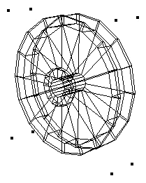
Procedure BeginSweep creates a three-dimensional sweep object in the Vectorworks document. A sweep object is a two-dimensional template object which has been rotated about a specified point to create a 3D object. For example, a circle of radius 1" that is swept about a point 2" to the right of the circles center wil create a sweep object resembling a donut, also known as a torus.

The sweep increment may also be thought of as the spacing between the duplication of radial sweep mesh lines. The "pitch", or vertical distance, is the distance that the sweep object will travel for every 360° of rotation. In sweep objects, the 2D template object may also be translated as it rotates, resulting in a "corkscrew" effect. The vertical movement is determined by the following equation: vertical movement = pitch * ArcAngle/360.

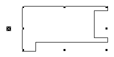
2D Object "Template" for Sweep


Sweep Object


説明

この手続きが実行した後、EndSweepが実行されるまでに作成された2次元図形をもとに回転体を作成します。

Parameters:

startAngle Starting angle of the sweep. 回転体の開始角度
arcAngle Angle of sweep. 回転体の角度
incAngle Increment of sweep. 回転体の分割数
PitchDistance Pitch (translation distance) of sweep. 回転体の上下方向のずれ

Example:

BeginSweep(#0d,#360d,#10d,0');
  Poly(3 1/4",-1/2",
       3 1/4",-1",
       2 3/4",-1",
       2 1/4",-1/2",
       2 1/4",1",
       1 3/4",1 1/2",
       -1 3/4",1 1/2",
       -2 1/4",1",
       -2 1/4",-1/2",
       -2 3/4",-1",
       -3 1/4",-1",
       -3 1/4",-1/2",
       -2 3/4",0",
       -2 3/4",1 1/2",
       -2 1/4",2",
       2 1/4",2",
       2 3/4",1 1/2",
       2 3/4",0");
EndSweep;


  BeginXtrd Objects - 3D 
MiniCAD

VectorScript Declaration:

PROCEDURE   BeginXtrd
(   startDistance :REAL (Coordinate);
    endDistance :REAL (Coordinate)
) ;

Python:

def  vs.BeginXtrd(startDistance, endDistance):
   return None

Description:

Procedure BeginXtrd creates a 3D extrude object in a Vectorworks document. BeginXtrd uses 2D object creation procedure calls to define the "template" for the object.

You should call EndXtrd after the object creation procedures to complete the definition and generate the extrude object in the document.


説明

この手続きを実行した後、EndXtrdが実行されるまでに作成された2次元図形を底面とする柱状体を作成します。

Parameters:

startDistance Start distance from document ground plane. 立ち上がりの高さ
endDistance End distance from document ground plane. 柱状体の高さ

Example:

BeginXtrd(0',4');
Rect(-1 61/64",125/128",-1 119/256",-375/512");
Rect(-1 113/512",1 113/512",-375/512",-125/256");
Rect(-125/256",125/128",0',-375/512");
Rect(125/128",125/128",1 119/256",-375/512");
Rect(1 25/512",1 113/512",375/512",-125/256");
Rect(1 363/512",1 113/512",2 101/512",-125/256");
EndXtrd;
{creates an extrude using the defined rectangles, each extruded to a depth of 4'}


  Centroid3D Objects - 3D 
VectorWorks10.1

VectorScript Declaration:

FUNCTION   Centroid3D
(   object :HANDLE;
  VAR  xCG :REAL;
  VAR  yCG :REAL;
  VAR  zCG :REAL
) :BOOLEAN ;

Python:

def  vs.Centroid3D(object):
   return (BOOLEAN, xCG, yCG, zCG)

Description:

Returns the center of gravity of a 3D object. The function returns TRUE if the values were found.

説明

ハンドルで指定した3次元図形の質量中心の座標を返します。計算できた場合は、TRUEを返します。

Parameters:

object The objectt from whci to calculate the center of gravity 図形のハンドル
xCG The x component of the center of gravity. 質量中心のX座標
yCG The y component of the center of gravity. 質量中心のY座標
zCG The z component of the center of gravity. 質量中心のZ座標

Result:

Returns true if the function succeeds.

返り値

TRUE:質量中心の座標を返しました。
FALSE:質量中心の座標を返せませんでした。


  ConvertTo3DPolys Objects - 3D 
VectorWorks10.0

VectorScript Declaration:

FUNCTION   ConvertTo3DPolys
( original:HANDLE ) :HANDLE ;

Python:

def  vs.ConvertTo3DPolys(original):
   return HANDLE

Description:

Converts an object to 3D polygons. This function successfully converts rectangles, circles, arcs, polylines, polygons, ovals, lines, straight walls, curved walls, and roofs.

説明

ハンドルで指定した図形(四角形、円、円弧、曲線、多角形、長円、線、壁、円弧壁、屋根)を3D多角形に変換します。

Parameters:

original Handle to the original object. 図形のハンドル

Example:

PROCEDURE Example;
VAR
	h :HANDLE;
BEGIN
	h := ConvertTo3DPolys(FSActLayer);
END;
RUN(Example);


  CreateContourCurves Objects - 3D 
VectorWorks10.1

VectorScript Declaration:

FUNCTION   CreateContourCurves
(   inSourceObject :HANDLE;
    delta :REAL;
    ptOnPlaneX :REAL;
    ptOnPlaneY :REAL;
    ptOnPlaneZ :REAL;
    normalX :REAL;
    normalY :REAL;
    normalZ :REAL
) :HANDLE ;

Python:

def  vs.CreateContourCurves(inSourceObject, delta, ptOnPlane, normal):
   return HANDLE

Description:

Creates contour curves for a solid object given the delta, point on plane and plane normal. If delta is 0, only 1 curve is created, where the specified plane intersects the selected solid.

説明

ハンドルで指定したソリッド図形に、指定した間隔で等高線を作成します。

Parameters:

inSourceObject Handle to a solid object ソリッド図形のハンドル
delta Distance between contours 等高線の間隔
ptOnPlane Point on plane used to define contours 等高線を定義するために使われている平面上の点の座標
normal Plane's normal vector 平面の法線ベクトル

Result:

Returns a HANDLE to a group containing NURBS curves representing the contours.

返り値

等高線を表すNURBS曲線のグループへのハンドル

Example:

PROCEDURE Example;
VAR
	inSourceObject :HANDLE; 
	delta :REAL; 
	ptOnPlaneX, ptOnPlaneY, ptOnPlaneZ :REAL; 
	normalX, normalY, normalZ :REAL;
	h :HANDLE;
BEGIN
	inSourceObject := FSActLayer;
	delta := 0; {number of slices}
	ptOnPlaneX := 0;
	ptOnPlaneY := 0;
	ptOnPlaneZ := 610;
	normalX := 0;
	normalY := 0;
	normalZ := 1;
	h := CreateContourCurves(inSourceObject, delta, ptOnPlaneX, ptOnPlaneY, ptOnPlaneZ, normalX, normalY, normalZ);
END;
RUN(Example);


  CreateExtrudeAlongPath Objects - 3D 
VectorWorks9.0

VectorScript Declaration:

FUNCTION   CreateExtrudeAlongPath
(   pathHandle :HANDLE;
    profileHandle :HANDLE
) :HANDLE ;

Python:

def  vs.CreateExtrudeAlongPath(pathHandle, profileHandle):
   return HANDLE

Description:

Creates a new path extrude object in the document. The profile defines the shape of the cross-section, and is extruded along the path to generate the resulting object.

The path argument must be a handle to a NURBS Curve object (type 111). The profile argument must be a handle to an object of one of the following types: NURBS Curve, Polygon, Polyline, Arc, Rectangle, Rounded Rectangle, Line, Oval.

説明

輪郭、パスを示す図形から3Dパス図形を作成します。
パスの図形属性はNURBS曲線(111)でなければなりません。
輪郭の図形属性はNURBS曲線、多角形、曲線、円弧、四角形、隅の丸い四角形、線、長円でなければなりません。

Parameters:

pathHandle Handle to the path object. パスのハンドル(NURBS曲線)
profileHandle Handle to the profile object. 輪郭のハンドル

Result:

Returns a HANDLE to the new path extrude if successful, otherwise returns NIL.

返り値

新しく作成された3Dパス図形のハンドルを返します。その他の場合はNILを返します。

See Also:

ExtrudeAlongPath  


  CreateImageProp Objects - 3D 
VectorWorks11.5

VectorScript Declaration:

FUNCTION   CreateImageProp
(   propName :STRING;
    textureRef :LONGINT;
    height :REAL;
    width :REAL;
    enforceImageAspectRatio :BOOLEAN;
    crossedPlanes :BOOLEAN;
    createPlugin :BOOLEAN;
    autoRotate :BOOLEAN;
    createSymbol :BOOLEAN
) :HANDLE ;

Python:

def  vs.CreateImageProp(propName, textureRef, height, width, enforceImageAspectRatio, crossedPlanes, createPlugin, autoRotate, createSymbol):
   return HANDLE

Description:

Create an image prop from the options specified.

The texture resource and optional symbol created will use names derived from the propName parameter. If those names are being used then unique names will be assigned. If enforceImageAspectRatio is true, depending on deriveWidthFromHeight the prop width/height will be derived from the prop height/width and the texture's image aspect ratio. Otherwise the height and width can be set independently of the texture's image aspect ratio.

説明

オプションを指定して添景を作成します。
propNameパラメータで指定した名前をもつテクスチャとシンボルが作成されます。名前が既に使われている場合は固有の名前をつけられます。enforceImageAspectRatioパラメータがTRUEの場合、イメージの縦横比を固定します。FALSEの場合、イメージの高さ、横幅を自由に設定できます。


  CreateTaperedExtrd2 Objects - 3D 
Vectorworks 2016

VectorScript Declaration:

FUNCTION   CreateTaperedExtrd2
(   profileH :HANDLE;
    angle :REAL;
    height :REAL
) :HANDLE ;

Python:

def  vs.CreateTaperedExtrd2(profileH, angle, height):
   return HANDLE

Description:

Creates a new tapered extrude object in the document. This function returns a "general solid" object while the other function, CreateTaperedExtrude, produces a bunch of NURBS surfaces.

説明

錐状体を作成します。CreateTaperedExtrudeでは複数のNURBS曲面となり、CreateTaperedExtrd2では汎用ソリッドとなります。

Parameters:

profileH Handle to object defining profile geometry. 底面図形のハンドル
angle Taper angle of extrude (in degrees). 角度
height Height of extrude. 高さ

Result:

Returns a HANDLE to the new tapered extrude if successful, otherwise returns NIL.

返り値

新しく作成された錐状体のハンドルを返します。その他の場合はNILを返します。


  CreateTaperedExtrude Objects - 3D 
VectorWorks9.0

VectorScript Declaration:

FUNCTION   CreateTaperedExtrude
(   profileH :HANDLE;
    angle :REAL;
    height :REAL
) :HANDLE ;

Python:

def  vs.CreateTaperedExtrude(profileH, angle, height):
   return HANDLE

Description:

Creates a new tapered extrude object in the document.

説明

錐状体を作成します。CreateTaperedExtrudeでは複数のNURBS曲面となり、CreateTaperedExtrd2では汎用ソリッドとなります。

Parameters:

profileH Handle to object defining profile geometry. 底面図形のハンドル
angle Taper angle of extrude (in degrees). 角度
height Height of extrude. 高さ

Result:

Returns a HANDLE to the new tapered extrude if successful, otherwise returns NIL.

返り値

新しく作成された錐状体の一部のハンドルを返します。その他の場合はNILを返します。


  EndMesh Objects - 3D 
MiniCAD

VectorScript Declaration:

PROCEDURE   EndMesh
;

Python:

def  vs.EndMesh():
   return None

Description:

Procedure EndMesh completes the definition of a mesh object within a Vectorworks document. On calling EndMesh, the mesh is created in the document from the preceding object creation calls.

It is recommended to call ResetOrientation3D after 3D object creations in order to ensure that the new 3D objects will draw properly.


説明

BeginMeshを実行した後、この手続きが実行されるまでに作成された図形をもとにメッシュ図形を作成します。

Example:

BeginMesh;
ClosePoly;
PenSize(1);
PenPat(2);
FillPat(0);
Poly3D(0',0',4'-0",4'-0",0',4'-0",4'-0",-4'-0",4'-0",0',-4'-0",4'-0");
Smooth(0);
Poly3D(0',0',0',4'-0",0',0',4'-0",-4'-0",0',0',-4'-0",0');
Smooth(0);
Poly3D(0',-4'-0",0',0',-4'-0",4'-0",0',0',4'-0",0',0',0');
Poly3D(4'-0",-4'-0",0',4'-0",-4'-0",4'-0",0',-4'-0",4'-0",0',-4'-0",0');
Poly3D(4'-0",0',0',4'-0",0',4'-0",4'-0",-4'-0",4'-0",4'-0",-4'-0",0');
Poly3D(0',0',0',0',0',4'-0",4'-0",0',4'-0",4'-0",0',0');
EndMesh;


  EndMXtrd Objects - 3D 
MiniCAD

VectorScript Declaration:

PROCEDURE   EndMXtrd
;

Python:

def  vs.EndMXtrd():
   return None

Description:

Procedure EndMXtrd completes the definition of a multiple extrude object within a Vectorworks document. On calling EndMXtrd, the object is created in the document from the preceding object creation calls.

It is recommended to call ResetOrientation3D after 3D object creations in order to ensure that the new 3D objects will draw properly.

説明

BeginMXtrdを実行した後、この手続きが実行されるまでに作成された2次元図形をもとに多段柱状体を作成します。

Example:

BeginMXtrd(0',1 363/512");
  Rect(-125/128",1 113/512",375/512",375/512");
  Rect(-25/32",1 113/512",275/512",375/512");
  Rect(-75/128",1 113/512",325/1024",375/512");
  Locus(-275/2048",125/128");
  Rect(-75/128",1 113/512",325/1024",375/512");
  Rect(-25/32",1 113/512",275/512",375/512");
  Rect(-125/128",1 113/512",375/512",375/512");
EndMXtrd;


  EndPoly3D Objects - 3D 
MiniCAD

VectorScript Declaration:

PROCEDURE   EndPoly3D
;

Python:

def  vs.EndPoly3D():
   return None

Description:

Procedure EndPoly3D completes the definition of a multiple extrude object within a Vectorworks document. On calling EndPoly3D, the object is created in the document from the preceding object creation calls.

It is recommended to call ResetOrientation3D after 3D object creations in order to ensure that the new 3D objects will draw properly.


説明

BeginPoly3Dを実行した後、この手続きを実行するまでに実行されたAdd3DPを頂点とする3D多角形を作成します。

Example:

BeginPoly3D;
     Add3DPt(0,0,0);
     Add3DPt(2,0,0);
     Add3DPt(2,2,0);
     Add3DPt(1,3,0);
     Add3DPt(0,2,0);
     Add3DPt(0,0,0);
EndPoly3D;

See Also:

BeginPoly3D   Add3DPt  


  EndSweep Objects - 3D 
MiniCAD

VectorScript Declaration:

PROCEDURE   EndSweep
;

Python:

def  vs.EndSweep():
   return None

Description:

Procedure EndSweep completes the definition of a sweep object within a Vectorworks document. On calling EndSweep, the object is created in the document from the preceding object creation calls.

It is recommended to call ResetOrientation3D after 3D object creations in order to ensure that the new 3D objects will draw properly.

説明

BeginSweepを実行した後、この手続きが実行されるまでに作成された2次元図形をもとに回転体を作成します。

Example:

BeginSweep(#0°,#360°,#10°,0');
  Poly(3 1/4",-1/2",3 1/4",-1",2 3/4",-1",
  2 1/4",-1/2",2 1/4",1",1 3/4",1 1/2",
  -1 3/4",1 1/2",-2 1/4",1",-2 1/4",-1/2",
  -2 3/4",-1",-3 1/4",-1",-3 1/4",-1/2",
  -2 3/4",0",-2 3/4",1 1/2",-2 1/4",2",
  2 1/4",2",2 3/4",1 1/2",2 3/4",0");
EndSweep;


  EndXtrd Objects - 3D 
MiniCAD

VectorScript Declaration:

PROCEDURE   EndXtrd
;

Python:

def  vs.EndXtrd():
   return None

Description:

Procedure EndXtrd completes the definition of an extrude object within a Vectorworks document. On calling EndXtrd, the object is created in the document from the preceding object creation calls.

It is recommended to call ResetOrientation3D after 3D object creations in order to ensure that the new 3D objects will draw properly.

説明

BeginXtrdが実行された後、この手続きが実行されるまでに作成された2次元図形を底面とする柱状体を作成します。

Example:

BeginXtrd(0',4');
 Rect(-1 61/64",125/128",-1 119/256",-375/512");
 Rect(-1 113/512",1 113/512",-375/512",-125/256");
 Rect(-125/256",125/128",0',-375/512");
 Rect(125/128",125/128",1 119/256",-375/512");
 Rect(1 25/512",1 113/512",375/512",-125/256");
 Rect(1 363/512",1 113/512",2 101/512",-125/256");
EndXtrd;


  ExtrudeAlongPath Objects - 3D 
Vectorworks 2014

VectorScript Declaration:

FUNCTION   ExtrudeAlongPath
(   pathHandle :HANDLE;
    profileHandle :HANDLE
) :HANDLE ;

Python:

def  vs.ExtrudeAlongPath(pathHandle, profileHandle):
   return HANDLE

Description:

Creates a new path extrude object in the document. The profile defines the shape of the cross-section, and is extruded along the path to generate the resulting object.

The path argument must be a handle to a NURBS Curve object (type 111). The profile argument must be a handle to an object of one of the following types: NURBS Curve, Polygon, Polyline, Arc, Rectangle, Rounded Rectangle, Line, Oval.

説明

3Dパス図形を作成します。輪郭をパスに沿って引き延ばした図形が作成されます。

パスの引数はNurbs曲線(図形タイプ111)である必要があります。輪郭は次のいずれかの図形です:Nurbs曲線、多角形、曲線、円弧、四角形、隅の丸い四角形、直線、楕円。

Parameters:

pathHandle Handle to the path object. パスのハンドル(NURBS曲線)
profileHandle Handle to the profile object. 輪郭のハンドル

Result:

Returns a generic solid HANDLE to the new path extrude if successful, otherwise returns NIL.

返り値

成功した場合は汎用ソリッドへのハンドルが返されます。そうでない場合はNILが返されます。

See Also:

CreateExtrudeAlongPath  


  Flip3DObj Objects - 3D 
Vectorworks 2010

VectorScript Declaration:

PROCEDURE   Flip3DObj
(   h :HANDLE;
    horiz :BOOLEAN
) ;

Python:

def  vs.Flip3DObj(h, horiz):
   return None

Description:

This function will flip a 3D object either horizontally or vertically. Its main use is for withing plugin objects when building their geometry and there is a need to mirror a piece.

The supported types are: Extrude, Sweep, MultiExtrude, Symbol, Mesh and CSGNode.

説明

3D図形をX軸かY軸で反転させる。

対象図形は、柱状体、多段柱状体、回転体、シンボル、メッシュ、オブジェクト

Parameters:

h The handle of the 3D object to flip. 図形のバンドル
horiz TRUE for a horizonal flip, FALSE for a vertical flip. 反転方向(TRUE:水平方向/FALSE:垂直方向)

Example:

PROCEDURE FlipTest;
{This script will create an extrude, dupicate it and then flip it horizontally}
VAR h1, h2 : HANDLE;

BEGIN

ClosePoly;

BeginXtrd(0', 4');
    BeginPoly;
	AddPoint( -5', 3' );
	AddPoint( 0, 3' );
	AddPoint( 0, 6' );
	AddPoint( 5', 0 );
	AddPoint( 0, -6');
	AddPoint( 0', -3');
	AddPoint(-5', -3');
    EndPoly;
EndXtrd;

h1 := LNewObj;


Move3DObj( h1, 5', 0 , 0 );
h2 := CreateDuplicateObject( h1, NIL );

Flip3DObj( h2 , TRUE );
Move3DObj( h2, -5', 0, 0 );

END;

Run(FlipTest);


  Get3DCntr Objects - 3D 
MiniCAD

VectorScript Declaration:

PROCEDURE   Get3DCntr
(   h :HANDLE;
  VAR  pX :REAL;
  VAR  pY :REAL;
  VAR  zValue :REAL
) ;

Python:

def  vs.Get3DCntr(h):
   return (p, zValue)

Description:

Procedure Get3DCntr returns the three-dimensional center point of the referenced 3D object.

説明

ハンドルで指定した3次元図形の中心の座標を返します。

Parameters:

h Handle to object. 3次元図形のハンドル
p Returns coordinates of object center point. 3次元図形の中心の座標(X、Y)
zValue Returns elevation of object center point. 3次元図形の中心の座標(Z)

Example:

PROCEDURE IncreaseExtr;
	{This script increases extruded objects in the selection by a user requested value.}
	{by Paolo, on the VectorScript bulletin board}
VAR
	oggetto :HANDLE;
	increaseValue :REAL;

FUNCTION Increase(h :HANDLE) :BOOLEAN;
VAR
	height, width, depth :REAL;
	xRot, yRot, zRot :REAL;
	p0X, p0Y, p0Z :REAL;
	p1X, p1Y, p1Z :REAL;
	result, isMirroredXY :BOOLEAN;
BEGIN
	{check if the obj is an extrusion}
	if (GetType(h) = 24) THEN BEGIN
		result := Get3DOrientation(h, xRot, yRot, zRot, isMirroredXY);
		Get3DCntr(h, p0X, p0Y, p0Z);
		
		SetRot3D(h, 0, 0, 0, 0, 0, 0);
		{here depth = extrusion value}
		Get3DInfo(h, height, width, depth);
		
		{I increase the depth}
		SET3DInfo(h, height, width, depth + increaseValue);

		SET3DRot(h, xRot, yRot, zRot , 0,0,0);
		
		Get3DCntr(h, p1X, p1Y, p1Z);
		
		{move of the misplacement p0-p1}
		Move3DObj(h, p0X-p1X, p0Y-p1Y, p0Z-p1Z);
		Get3DCntr(h, p1X, p1Y, p1Z);
	END;
	increase := FALSE;
END;

BEGIN
	{ask the value to increase}
	increaseValue := RealDialog('Increase extrusions in the selection of this value','10');
	{apply to the selected set of objects}
	ForEachObjectInList(increase, 2, 0, oggetto);
END;
RUN(IncreaseExtr);


  Get3DInfo Objects - 3D 
MiniCAD

VectorScript Declaration:

PROCEDURE   Get3DInfo
(   h :HANDLE;
  VAR  height :REAL;
  VAR  width :REAL;
  VAR  depth :REAL
) ;

Python:

def  vs.Get3DInfo(h):
   return (height, width, depth)

Description:

Procedure Get3DInfo returns the height, width and depth values of the referenced 3D object.

説明

ハンドルで指定した3次元図形の高さ、幅、奥行きを返します。

Parameters:

h Handle to 3D object. 3次元図形のハンドル
height Height of object. 3次元図形の高さ
width Width of object. 3次元図形の幅
depth Depth of object. 3次元図形の奥行き

Example:

PROCEDURE GetBBox3D(h :HANDLE; VAR x1, y1, z1, x2, y2, z2 :REAL);
VAR
	garb_r, z_span, z_center :REAL;
BEGIN
	GetBBox(h, x1, y1, x2, y2);
	Get3DInfo(h, garb_r, garb_r, z_span);
	Get3DCntr(h, garb_r, garb_r, z_center);
	z1 := z_center - (z_span / 2);
	z2 := z_center + (z_span / 2);
END;


  Get3DOrientation Objects - 3D 
VectorWorks8.0

VectorScript Declaration:

FUNCTION   Get3DOrientation
(   h :HANDLE;
  VAR  xRot :REAL;
  VAR  yRot :REAL;
  VAR  zRot :REAL;
  VAR  isMirroredXY :BOOLEAN
) :BOOLEAN ;

Python:

def  vs.Get3DOrientation(h):
   return (BOOLEAN, xRot, yRot, zRot, isMirroredXY)

Description:

Function Get3DOrientation returns the 3D orientation of the referenced object.

If the object is mirrored, a reflection across the X-Y plane must be applied before rotating by the angles above in order to reproduce the object's orientation.

説明

ハンドルで指定した3次元図形の回転角度を返します。

Parameters:

h Handle to 3D object. 3次元図形のハンドル
xRot Returns X rotation value. X軸の回転角度
yRot Returns Y rotation value. Y軸の回転角度
zRot Returns Z rotation value. Z軸の回転角度
isMirroredXY Returns mirror status of object. XY軸の反転

Result:

Get3DOrientation returns TRUE if a valid 3D object was passed to the procedure.

返り値

値が取得できた時はTRUEを返します。


  GetLocus3D Objects - 3D 
MiniCAD6.0

VectorScript Declaration:

PROCEDURE   GetLocus3D
(   h :HANDLE;
  VAR  pX :REAL;
  VAR  pY :REAL;
  VAR  pZ :REAL
) ;

Python:

def  vs.GetLocus3D(h):
   return p

Description:

Procedure GetLocus3D returns the coordinates of the referenced 3D locus object.

説明

ハンドルで指定した3D基準点の座標を返します。

Parameters:

h Handle to 3D locus. 3D基準点のハンドル
p Returns 3D coordinates of locus. 座標


  GetMeshVertex Objects - 3D 
Vectorworks 2012

VectorScript Declaration:

PROCEDURE   GetMeshVertex
(   hMesh :HANDLE;
    index :INTEGER;
  VAR  outPtX :REAL;
  VAR  outPtY :REAL;
  VAR  outPtZ :REAL
) ;

Python:

def  vs.GetMeshVertex(hMesh, index):
   return outPt

Description:

Return the specified vertex of a mesh object.

説明

メッシュオブジェクトの指定された頂点を返します。

Parameters:

hMesh Handle to the mesh object. メッシュオブジェクトのハンドル
index The Index of the vertex. 頂点のインデックス。
outPt Output parameter. The 3D coordinates of the vertex. 出力パラメータ:頂点の3D座標。

See Also:

GetMeshVertsCnt   GetMeshVertex   SetMeshVertex  


  GetMeshVertsCnt Objects - 3D 
Vectorworks 2012

VectorScript Declaration:

FUNCTION   GetMeshVertsCnt
( hMesh:HANDLE ) :INTEGER ;

Python:

def  vs.GetMeshVertsCnt(hMesh):
   return INTEGER

Description:

Returns the number of vertices of the passed mesh handle.

説明

渡されたメッシュハンドルの頂点の数を返します。

Parameters:

hMesh Handle to the mesh object. メッシュオブジェクトのハンドル

See Also:

GetMeshVertsCnt   GetMeshVertex   SetMeshVertex  


  GetPolyPt3D Objects - 3D 
MiniCAD7.0

VectorScript Declaration:

PROCEDURE   GetPolyPt3D
(   objectHd :HANDLE;
    index :INTEGER;
  VAR  pX :REAL;
  VAR  pY :REAL;
  VAR  pZ :REAL
) ;

Python:

def  vs.GetPolyPt3D(objectHd, index):
   return p

Description:

Procedure GetPolyPt3D returns the coordinates of the specified vertex of the referenced mesh, 3D polygon, or NURBS curve object.

Error checking for valid index values must be provided by the programmer.

説明

ハンドルで指定したメッシュ、3D多角形、NURBS曲線の指定した頂点番号の座標を返します。

Parameters:

objectHd Handle to 3D mesh or polygon. メッシュ、3D多角形、NURBS曲線のハンドル
index Index of vertex (range of 0 to n-1). 頂点番号(0からn-1の範囲)
p Returns 3D coordinates of vertex. 頂点の座標

Example:

for i := 0 to (GetVertNum(thePoly) - 1) do
begin		
	GetPolyPt3D(thePoly, i, vertX, vertY, vertZ);
end;	


  HExtrude Objects - 3D 
VectorWorks10.0

VectorScript Declaration:

FUNCTION   HExtrude
(   objectH :HANDLE;
    bottom :REAL;
    top :REAL
) :HANDLE ;

Python:

def  vs.HExtrude(objectH, bottom, top):
   return HANDLE

Description:

Creates an extrude object from the specified object.

説明

柱状体を作成します。

Parameters:

objectH The profile to be extruded. 図形のハンドル
bottom The z height of the bottom of the extrude. 柱状体の底面の高さ
top The z height of the top of the extrude. 柱状体の上面の高さ

Result:

A handle to the newly created extrude object.

返り値

新しく作成された柱状体のハンドルを返します。


  Locus3D Objects - 3D 
MiniCAD6.0

VectorScript Declaration:

PROCEDURE   Locus3D
(   pX :REAL;
    pY :REAL;
    pZ :REAL
) ;

Python:

def  vs.Locus3D(p):
   return None

Description:

Procedure Locus3D creates a new 3D locus in the document at the specified 3D coordinate location.

説明

座標を指定して3D基準点を作成します。

Parameters:

p 3D coordinates of new locus. X、Y、Z座標


  MeshToGroup Objects - 3D 
VectorWorks10.0

VectorScript Declaration:

FUNCTION   MeshToGroup
( meshObj:HANDLE ) :HANDLE ;

Python:

def  vs.MeshToGroup(meshObj):
   return HANDLE

Description:

Converts meshObj to a group of 3D polygons.

説明

ハンドルで指定したメッシュ図形を3D多角形で構成されたグループ図形に変換します。

Parameters:

meshObj Handle to a mesh object メッシュ図形のハンドル

Result:

Returns a handle containing 3D polygons.

返り値

3D多角形で構成されたグループ図形のハンドルを返します。

See Also:

GroupToMesh  


  Moments3D Objects - 3D 
VectorWorks10.1

VectorScript Declaration:

FUNCTION   Moments3D
(   object :HANDLE;
  VAR  lxx :REAL;
  VAR  lyy :REAL;
  VAR  lzz :REAL
) :BOOLEAN ;

Python:

def  vs.Moments3D(object):
   return (BOOLEAN, lxx, lyy, lzz)

Description:

Returns the moments of inertia of a 3D object about the x, y, and z axes of a point at the center of gravity of the object.

説明

図形の質量中心を通る軸での慣性モーメントを返します。

Parameters:

object The object for which to find the 3D moments. 図形のハンドル
lxx The moment of inertia relative to the x-axis passing through the center of mass of object X軸方向の慣性モーメント
lyy The moment of inertia relative to the y-axis passing through the center of mass of object Y軸方向の慣性モーメント
lzz The moment of inertia relative to the z-axis passing through the center of mass of object Z軸方向の慣性モーメント

Result:

Returns true if the function succeeded.

返り値

TRUE:慣性モーメントを返しました。
FALSE:慣性モーメントを返せませんでした。


  Poly3D Objects - 3D 
MiniCAD

VectorScript Declaration:

PROCEDURE   Poly3D
(   p :REAL
) ;

Python:

def  vs.Poly3D(p):
   return None

Description:

Procedure Poly3D creates a three dimensional polygon in a Vectorworks document. The vertices of the polygon are specified by a list of parameters x1, y1, z1 through xn, yn, and zn, which specify the coordinate locations of each vertex.

説明

座標を指定して3D多角形を作成します。

Example:

Poly3D(1,1,0,1.5,1.5,1,2.5,1.5,1,);


  Products3D Objects - 3D 
VectorWorks10.1

VectorScript Declaration:

FUNCTION   Products3D
(   object :HANDLE;
  VAR  lxy :REAL;
  VAR  lyz :REAL;
  VAR  lzx :REAL
) :BOOLEAN ;

Python:

def  vs.Products3D(object):
   return (BOOLEAN, lxy, lyz, lzx)

Description:

Returns the products of inertia of a 3D object for the xy, yz, and zx planes passing through a point at the center of gravity of the object.

説明

図形の質量中心を通る平面での慣性乗数を返します。

Parameters:

object The object from which to calculate the Products 図形のハンドル
lxy Theh product of inertia with respect to the YZ and XZ planes passing through the center of mass of object. XY平面の慣性乗数
lyz Theh product of inertia with respect to the XZ and XY planes passing through the center of mass of object. YZ平面の慣性乗数
lzx Theh product of inertia with respect to the XY and YZ planes passing through the center of mass of object. ZX平面の慣性乗数

Result:

Returns true if the function succeeds.

返り値

TRUE:慣性乗数を返しました。
FALSE:慣性乗数を返せませんでした。


  Set3DInfo Objects - 3D 
MiniCAD

VectorScript Declaration:

PROCEDURE   Set3DInfo
(   h :HANDLE;
    heightDistance :REAL (Coordinate);
    widthDistance :REAL (Coordinate);
    depthDistance :REAL (Coordinate)
) ;

Python:

def  vs.Set3DInfo(h, heightDistance, widthDistance, depthDistance):
   return None

Description:

Procedure Set3DInfo sets the height, width and depth dimensions of the referenced object.

説明

ハンドルで指定した3次元図形の高さ、幅、奥行きを変更します。

Parameters:

h Handle to 3D object. 3次元図形のハンドル
heightDistance New height of object. 3次元図形の高さ
widthDistance New width of object. 3次元図形の幅
depthDistance New depth of object. 3次元図形の奥行き


  Set3DRot Objects - 3D 
MiniCAD

VectorScript Declaration:

PROCEDURE   Set3DRot
(   h :HANDLE;
    xAngle :REAL;
    yAngle :REAL;
    zAngle :REAL;
    xDistance :REAL (Coordinate);
    yDistance :REAL (Coordinate);
    zDistance :REAL (Coordinate)
) ;

Python:

def  vs.Set3DRot(h, xAngle, yAngle, zAngle, xDistance, yDistance, zDistance):
   return None

Description:

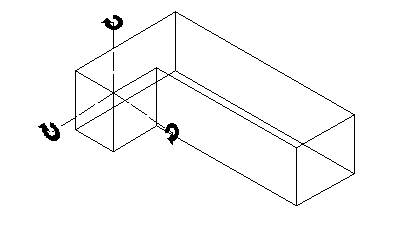
Procedure Set3DRot rotates the referenced 3D object about a specified 3D point. It works with the following 3D objects: extrude, multiple extrude, sweep, mesh, 3D polygon, solid, CSG solid, group, symbol, plug-in object, NURBS curve, NURBS surface.


The difference between Set3DRot and SetRot3D is that Set3DRot adds the specified rotation to the existing rotation of the object, whereas SetRot3D does not consider the existing rotation, and merely makes the object rotation match the specified values.

説明

ハンドルで指定した3次元図形を、指定した回転軸を中心に回転させます。
柱状体、多段柱状体、回転体、メッシュ、3D多角形、ソリッド、ソリッドモデラー、グループ、シンボル、プラグインオブジェクト、NURBS曲線、NURBS曲面で利用できます。

「Set3DRot」と「SetRot3D」の違いは、以下のとおりです。
「Set3DRot」は図形を現在の角度から指定した角度分回転させます。
「SetRot3D」は図形の角度を指定した角度にします。

Parameters:

h Handle to 3D object. 3次元図形のハンドル
xAngle X axis rotation angle. X軸方向の回転角度
yAngle Y axis rotation angle. Y軸方向の回転角度
zAngle Z axis rotation angle. Z軸方向の回転角度
xDistance X coordinate of center of rotation. 回転軸のX座標
yDistance Y coordinate of center of rotation. 回転軸のY座標
zDistance Z coordinate of center of rotation. 回転軸のZ座標

Example:

Set3DRot(hd,10d,30d,23d45',3,3,2);

See Also:

SetRot3D  


  SetMeshVertex Objects - 3D 
Vectorworks 2012

VectorScript Declaration:

PROCEDURE   SetMeshVertex
(   hMesh :HANDLE;
    index :INTEGER;
    ptX :REAL;
    ptY :REAL;
    ptZ :REAL
) ;

Python:

def  vs.SetMeshVertex(hMesh, index, pt):
   return None

Description:

Set a mesh vertex.

説明

メッシュの頂点を設定します。

Parameters:

hMesh Handle to the mesh object. メッシュオブジェクトのハンドルを指定します。
index The Index of the vertex. 頂点のインデックス。
pt The new vertex coordinates. 新しい頂点座標。

See Also:

GetMeshVertsCnt   GetMeshVertex   SetMeshVertex  


  SetPolyPt3D Objects - 3D 
MiniCAD7.0

VectorScript Declaration:

PROCEDURE   SetPolyPt3D
(   objectHd :HANDLE;
    index :INTEGER;
    pX :REAL;
    pY :REAL;
    zValue :REAL
) ;

Python:

def  vs.SetPolyPt3D(objectHd, index, p, zValue):
   return None

Description:

Procedure SetPolyPt3D sets the position of the specified vertex in the referenced 3D object.

説明

ハンドルで指定した3D多角形の指定した頂点番号の座標を変更します。

Parameters:

objectHd Handle to mesh or 3D poly object. 3D多角形のハンドル
index Index of vertex point. 頂点番号
p New X-Y coordinates of vertex. 頂点のX、Y座標
zValue New elevation of vertex. 頂点のZ座標

Example:

SetPolyPt3D(objectHandle,3,2.5",3",8");


  SetRot3D Objects - 3D 
MiniCAD

VectorScript Declaration:

PROCEDURE   SetRot3D
(   h :HANDLE;
    xAngle :REAL;
    yAngle :REAL;
    zAngle :REAL;
    xDistance :REAL (Coordinate);
    yDistance :REAL (Coordinate);
    zDistance :REAL (Coordinate)
) ;

Python:

def  vs.SetRot3D(h, xAngle, yAngle, zAngle, xDistance, yDistance, zDistance):
   return None

Description:

Procedure SetRot3D sets the rotation (in degrees) of the referenced object to the specified rotations and center. This procedure works on the following 3D objects: extrudes, multiple extrudes, and sweeps.


The difference between Set3DRot and SetRot3D is that Set3DRot adds the specified rotation to the existing rotation of the object, whereas SetRot3D does not consider the existing rotation, and merely makes the object rotation match the specified values.

説明

ハンドルで指定した3次元図形を、指定した角度(度数)と軸で回転させます。
柱状体、多段柱状体、回転体で利用できます。

「Set3DRot」と「SetRot3D」の違いは、以下のとおりです。
「Set3DRot」は図形を現在の角度から指定した角度分回転させます。
「SetRot3D」は図形の角度を指定した角度にします。

Parameters:

h Handle to 3D object. 3次元図形のハンドル
xAngle New X rotation angle. X軸方向の角度
yAngle New Y rotation angle. Y軸方向の角度
zAngle New Z rotation angle. Z軸方向の角度
xDistance X coordinate of rotation center. 回転軸のX座標
yDistance Y coordinate of rotation center. 回転軸のY座標
zDistance Z coordinate of rotation center. 回転軸のZ座標

See Also:

Set3DRot